

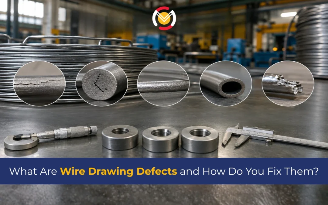
Wire drawing defects are flaws that appear during the wire manufacturing process on the surface, inside the wire, or in its dimensions. Surface cracks, internal voids, diameter variation, and wire breakage are the most common types. Each one has a specific cause, and each one has a fix.
The most common wire-drawing defects include the following:
- Surface cracks and die lines caused by worn dies or poor lubrication
- Internal voids and chevron cracking from excessive reduction ratios
- Diameter variation and ovality from unstable drawing speed or worn tooling
- Wire breakage from high tensile stress or improper die angle
Why Do Wire Drawing Defects Cost You More Than You Think?
You lose more than just wire when defects show up on the production floor. You lose time, material, and, in a B2B setup, customer confidence.
One batch of defective wire can trigger a full line stoppage. In high-volume manufacturing, that translates directly to missed deadlines and rejected orders. The frustrating part? Most wire-drawing defects are preventable. They come from a handful of root causes that repeat across facilities: worn dies, diamond dies, wrong lubrication, bad reduction ratios, and unstable drawing speeds.
Understanding where each defect comes from is the first step. Fixing the process comes second. And investing in the right machine setup? That is what stops the problem from coming back.
What Are the Main Types of Surface Defects in Wire Drawing?
Surface defects are the most visible wire-drawing defects, and they are usually the first sign that something is wrong in the process.
- Surface Cracks Cracks on the outer layer of the wire appear when the die is worn or the drawing speed is too high. The wire surface experiences uneven stress, and the material gives way. Regular die inspection catches these problems early.
- Scratches and Scoring Scratches occur when foreign particles enter the die zone. Contaminated lubricant or a dirty working environment are the usual reasons. A clean lubrication system and filtered drawing compounds reduce scoring significantly.
- Oxidation Marks These appear when the wire surface reacts with moisture or air during drawing. Poor sealing in the lubrication zone or inadequate cooling allows oxidation to set in. Proper cooling systems and enclosed lubricant application solve this.
Die lines are shallow grooves that run lengthwise on the wire. A damaged or improperly finished die is the cause. Replacing worn dies and using precision-ground tooling eliminates die lines at the source.
What Causes Internal Defects in Wire Drawing?
Internal wire drawing defects are harder to spot; they do not show on the surface. But they are often more damaging because they affect wire strength and reliability.
- Central Burst (Chevron Cracking): This is one of the most serious internal wire-drawing defects. Small chevron-shaped cracks form at the wire’s core when the reduction ratio is too high or the die angle is wrong. The metal at the centre cannot deform uniformly, so it fractures internally. Reducing the single-pass reduction ratio and correcting the die half-angle prevents central burst.
- Internal Voids: Voids inside the wire form when there is poor bonding between the metal’s internal grains during deformation. This phenomenon is often linked to low-quality rod material or insufficient intermediate annealing. Multi-pass drawing with controlled reductions gives the metal enough time to recover between passes.
- Residual Stress Concentration: When drawing speed or reduction is inconsistent, residual stress builds up unevenly inside the wire. This condition weakens the final product even if the surface looks fine. Stress relief through controlled annealing brings this under control.
What Dimensional Defects Show Up in Wire Drawing?
Dimensional wire-drawing defects affect the wire’s geometry, and in precision applications, even small deviations cause rejection.
- Diameter Variation The wire diameter fluctuates when drawing speed is unstable or the die wears unevenly. A consistent capstan speed and regular die replacement maintain diameter within tolerance.
- Ovality Ovality means the wire cross-section is not circular; one axis is wider than the other. Misaligned dies or uneven wire feed is the main culprit. Proper die alignment during setup and a consistent wire entry angle fix this problem.
- Inconsistent Tolerance When multiple passes have different speeds or when die geometry varies across a drawing line, the wire loses dimensional consistency from one end to the other. Calibrated speed control across all capstans and standardised die specifications bring tolerances back in line.
According to a study published in Wiley Online Library, crack propagation in wire drawing intensifies with larger inclusions and higher compression ratios, increasing the overall failure probability of the wire.
How Do You Prevent Wire Drawing Defects Before They Start?
Wire Expo 2026 made it evident that the industry is moving toward tighter quality benchmarks and higher production expectations simultaneously. For manufactu
Prevention costs far less than correction. Here is what leading wire manufacturers do differently:
- Control Drawing Speed and Reduction Ratio High speed with high reduction is a recipe for wire-drawing defects. Keep single-pass reductions within the recommended range for each material. Slow the line down before increasing reduction.
- Use the Right Lubrication System Lubrication does more than reduce friction; it protects the die, cools the wire, and prevents oxidation. Use the correct lubricant type for your wire material and keep the lubrication system clean and pressurised.
- Inspect Dies Regularly A worn die causes multiple wire-drawing defects at once: surface scratches, die lines, diameter variation, and ovality. Set a die-replacement schedule based on tonnage drawn, not just visual inspection.
- Apply Intermediate Annealing When Needed For materials that work-harden quickly, annealing between drawing passes relieves internal stress and restores ductility. Skipping this step to save time usually results in wire breakage or internal defects downstream.
- Train Operators on Process Consistency Machine settings alone do not prevent defects. Operators who understand the cause-and-effect relationship between drawing parameters and wire quality can identify issues before they escalate.
rers looking to stay ahead, a few areas deserve attention:
- Tooling audits to assess current die performance against production targets
- Material-specific die selection to match wire alloy, drawing lubricant, and production speed.
- Preventive die maintenance programs to extend service life and reduce unplanned downtime.
- Engagement with tooling specialists who can support both standard and custom die requirements.
Choosing the right tooling partner goes beyond product quality. Technical knowledge, application experience, and service responsiveness all contribute to long-term production performance.
What Machine Setup Reduces Wire Drawing Defects Most Effectively?
The machine you run is as important as the process you follow. Here is what to look for:
- Stable Speed Control System Speed fluctuations cause diameter variation and internal stress. A machine with precise, closed-loop speed control keeps the drawing process steady from first pass to last.
- High-Precision Die Alignment Misaligned dies lead to ovality and an uneven surface finish. Machines with rigid, adjustable die holders that lock into exact alignment reduce this risk.
- Efficient Lubrication System An integrated, pressurised lubrication system ensures that the die and wire interface remains protected throughout the draw. Machines with recirculating lubricant systems maintain consistent lubrication without manual adjustment.
- Strong Cooling System Heat build-up during drawing changes the wire’s mechanical properties and accelerates die wear. Effective cooling, especially in high-speed or multi-pass setups, keeps both the wire and the tooling within their optimal temperature range.
- Low Vibration Structure Machine vibration transfers to the wire as surface irregularities. A rigid, well-balanced machine frame dampens vibration and produces a cleaner wire surface.
Why Does Mikrotek Stand Out for Wire Drawing Solutions?
Wire Expo 2026 was a clear reflection of where the wire and cable industry is heading: faster production, tighter tolerances, and a sharper focus on tooling quality as a competitive differentiator. For manufactur
Mikrotek builds wire-drawing machines around the factors that prevent wire-drawing defects precise speed control, accurate die alignment, and integrated lubrication. Recurring issues like breakage, diameter variation, or surface cracking often trace back to the machine. Mikrotek addresses this issue at the design level.
Mikrotek offers a configuration for your needs, ranging from straight-line machines for high-precision output to continuous and wet wire-drawing machines designed for high-speed or breakage-sensitive production.
Ready to reduce wire drawing defects on your production line? Talk to Mikrotek today.
ers serious about consistent wire quality and efficient operations, the right die technology and the right tooling partner matter.
Explore Mikrotek’s range of precision wire drawing dies and tooling solutions to find the right fit for your production requirements.
FAQs
1. What is the most common wire-drawing defect in production?
Wire breakage and surface cracking are the most frequently reported wire-drawing defects on production floors. Both usually trace back to worn dies, insufficient lubrication, or a drawing speed that is too high for the reduction ratio being used. Fixing these two variables resolves the majority of recurring defect issues.
2. How does die angle affect wire-drawing defects?
The die half-angle directly influences how stress distributes inside the wire during drawing. A die angle that is too steep concentrates stress at the wire’s center and causes internal wire-drawing defects, such as chevron cracking. The correct angle depends on the material and the reduction ratio getting this right prevents both surface and internal defects.
3. Can wire drawing defects be detected without cutting the wire?
Yes. Non-destructive testing methods like eddy current testing detect surface and near-surface wire drawing defects without damaging the wire. For internal defects like central burst, ultrasonic testing provides reliable detection. These methods are used in quality control lines to catch defects before the wire ships.
4. How often should dies be replaced to prevent wire-drawing defects?
Die replacement frequency depends on the material being drawn, the drawing speed, and the reduction ratio. As a general guideline, dies should be inspected after every production run and replaced when wear on the bearing zone exceeds the tolerance for the wire diameter being produced. Waiting for visible defects before replacing dies is too late.
5. Does machine type affect the rate of wire drawing defects?
Yes, significantly. A wet wire drawing machine, for example, uses liquid lubricant throughout the draw, which substantially reduces friction-related wire drawing defects like surface scratches and breakage. A straight-line machine offers better die alignment and lower vibration, which reduces dimensional defects. Choosing the right machine type for your wire material and product specification is a critical decision.
6. What role does lubrication play in preventing wire drawing defects?
Lubrication reduces friction at the die zone, which prevents surface defects in wire drawing, such as scratches, die lines, and oxidation marks. It also controls heat build-up. Using the right lubricant and keeping the system clean eliminates a large share of surface defects.
7. How does multi-pass drawing reduce wire drawing defects?
Multi-pass drawing spreads total reduction across smaller passes, allowing the metal to deform uniformly at each stage. This prevents internal wire-drawing defects like central burst, reduces breakage risk, and produces a more consistent diameter compared to single-pass heavy reduction.
8. How does residual stress from wire drawing defects affect the final product?
Residual stress weakens the wire under load without showing on the surface. Uneven drawing speed or excessive reduction causes internal stress build-up, leading to spring-back, reduced fatigue life, and delayed cracking. Controlled annealing after drawing removes residual stress effectively.
9. How does Mikrotek help manufacturers reduce wire-drawing defects through machine design?
Mikrotek builds speed control, precision die alignment, and pressurised lubrication into every machine as standard. These features directly address the root causes of wire drawing defects, reducing the need for manual corrections on the production floor.
10. What should manufacturers look for in a Mikrotek wire-drawing machine to minimise defects?
Focus on speed control stability, lubrication system design, and cooling capacity. Mikrotek builds machines in straight-line, continuous, and drawing configurations around these priorities to reduce wire-drawing defects across different materials and production speeds.
